Before starting this section, make sure you have completed all of the steps in Soldering and all the software setup in Pi Config.
This guide is provided for informational and educational purposes only. While every effort has been made to ensure accuracy, the author accepts no responsibility for errors, omissions, or outcomes resulting from the use of this material. Building, soldering, programming, and operating electronic devices involve risks that include but are not limited to electric shock, burns, fire, or equipment damage. By following this guide, you assume full responsibility for your safety, your tools, your materials, and the final device. Always follow appropriate safety practices and proceed at your own risk.
WARNING: Please carefully follow the steps. Failure to do this correctly could cause damage to the Pi or worse. Pay careful attention when screwing in the handle or you will screw through a battery!
The handle is one of the easiest parts to assemble. Firstly you will need to remove all of the support material from inside the handle. Be careful not to snap off the screw posts too!
Once removed, the next thing is to file or sand down the area the button will slide in and out of as shown in the video below. You will also need to smooth the button too. If you don't do this then the button will stick when pressed.
Once smoother, the next task is to install the micro switch that you soldered up previously. The first thing you will need to do is install some M3 brass thread inserts into the holes on one side of the handle. These can be added by heating them up and pushing them gently into the plastic. I do this by screwing a screw through it and out the other side and then applying heat to the whole thing, then letting it cool down before unscrewing them again.
These can then be screwed in place using some M3 machine screws. after this you can route the cable out through the handle optionally with a little bit of hot glue to prevent the cable being pulled out.
Finally you can assemble the handle using the longer 25mm self tapping screws. Careful not to over-tighten these and check their length isn`t screwing through the other side!
If you have chosen to print the viewer in two separate colours, then the first step is to glue the main body together. If you have printed them as one piece and painted them then you can skip this step.
Next, we need to attach the viewer case to the main body of the tracker. First we glue the black/Viewer Angle Corrector piece onto the space in the side, such that when the viewer is sat on the table flat, the edge of the corrector is perfectly vertical: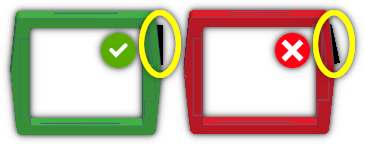
With that glued in place, and wait for the glue to dry, we finally get to attach it to the main body. Insert the black/Viewer Tube Pivot (Washer) part into the viewer from the inside, and on the outside, add a M16 Rubber Flat Washer 16mm (typically used with garden hoses). Finally, add some glue into the hole on the side of the body being careful not to get any on the side, and push the piece in. You need to hold it firmly, but not too hard such that the viewer can still rotate. Hold until the glue sets.
Next we need to install all of the electronics inside. Take time with this and don't rush it!
First we thread through the wires for the top and bottom panels, noting the different shapes on the cut outs for the various pieces and then thread the wires through to the main body.
Then thread the wires through for the LCD panel, keeping the big connector on the side of the viewer. It`s a tedious job, but with patience it can be done.
Next, bend the wires so they`re all flat, and insert the black/LCD Viewer piece from the front, carefully guiding the wires into the grooves on it. You might feel a little resistance doing this, be careful not to pinch any wires and it should slide into place.
Once it`s in place, secure the top and bottom panels in place with super glue after pulling any remaining cable through into the back of the viewer. If either panel doesn`t fit flat then you may need to bend contacts flat out of the way.
Once the glue is all set, and do make sure it has all dried it`s time to install the LCD panel. Make sure the panel is completely clean as you wont be able to get access to it again. Start by removing the screws in the four corners and gently remove the mounting posts. Then attach the wire to the connector on the back, peal off the protective film, and drop it into place. It should sit flush, level with the back, pulling through all of the excess cable into the body of the tracker.
Also, you may optionally want to add a small amount of padding to make sure the LCD panel doesn`t rattle around.
BEFORE you glue the back on, take a photo of the back of the LCD panel so you can see what colour wire goes to which pin, and the order that they are in.
Yours might not have the same colour wires, or be in the same order: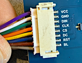
You can now glue the back panel or panels into place depending on if you have printed one piece or two separate pieces.
Tip: Don`t use superglue to stick the back on. The fumes from the glue may cloud the LCD panel! You may also want to use some tape to hold it all together while the glue sets. Be careful however, as the front isn't secured in place yet and could pop out!
Once the glue for the back has completely set, turn the viewer round so that the front is facing upwards, and after cleaning the lens, drop it into place, the curved side facing upwards, the flat side facing down.
Then glue the black/Viewer Front Cover No Supports over the front, making sure it is aligned perfectly. Once again, do not use super glue as the fumes may leave a smokey layer on the inside of the lens. Leave plenty of time for this to try, wiping off any excess glue.
Finally, we can add the button to the slider variable resistor. You will need to trim down the slider on the variable resistor to a suitable length, and then finally clip the button into place, optionally with a little bit of glue to secure it, being careful not to get any on the slider its self!
If you are adding the UV leds, its time to secure them into place. You need to thread their wires through a tiny hole in the green-brown/Top Section next to the hole for the fan, and then secure them in place, pointing towards the middle, with glue. You could use either super glue or hot glue here: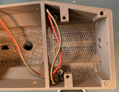
We`re going to complete some of the top of the motion tracker by adding the speaker and power switch. When soldering wires to the power switch, either use thicker wire, or join two of the dupont wires together for each contact.
Most of this just fits into place and is secured using two 12mm screws, and finally pushing the slider switch button into place. You shouldn`t need any glue for this making it easier to disassemble if anything goes wrong:
There are two parts that need fitting into the base. One is the volume control variable resistor, and the other is the USB-C style power connector.
NOTE: If you are using the 2-Wire USB-C connector, then it will only charge with dumb USB-C chargers or with USB-C to USB-A Cables.
Be sure to save the metal washer from the variable resistor, you will need it later for another part!
There are a few bits that need manually assembling, mostly for aesthetics, but still need completing regardless.
The first part attaches a knob (green-brown/Knob) to the thin (green-brown/TopBotom Join) along with the optional glow in the dark (optional/GlowBar) piece.
You will need a suitable M3 self tapping screw if using the GlowBar, and you insert the washer you saved from the previous section in-between the knob and thin piece. This allows it to turn easily. If you aren`t using the GlowBar then you may need to use an M3 bolt and nut.
There are a few other little bits that need assembling, and finally, they are screwed to the top section using two small M3 screws from the inside.
This video covers the preparation of several different parts that need assembling before attaching to the main body of the tracker. This includes the keypad, pump assembly and the top section of the tracker.
The order of content in this video may seem strange but its to emphasis that you need to allow time for glue to set!
The power supply is obviously important, and this video shows how it is wired up, along with the fan. The fan is designed to run when the unit is charging AND when the unit is powered up. This is achieved by using two DIODES that allow current to only flow through in one direction.
This is the basic circuit diagram for the power supply: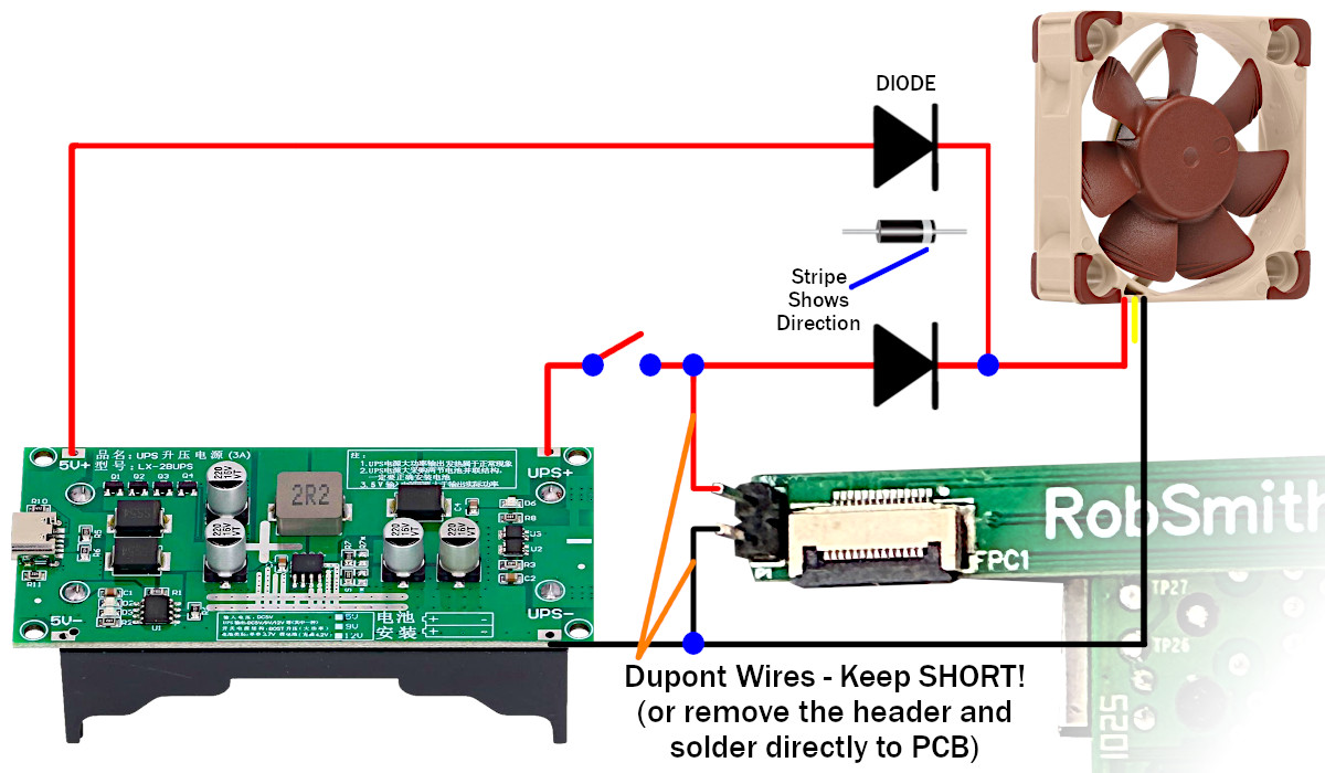
NOTES: The direction of the DIODEs are very important. Also, when connecting all of the power, please use either thicker wire, double up and use two per polarity, or keep them as short as possible! See power throttling.
PCB Polarity: Be 100% Sure you have the 5V/GND the correct way around when connecting power to the Raspberry Pi. There is NO protection. Incorrect polarity will damage the Raspberry Pi! GND is the side the flat cable exits the connector.
This first video shows how the fan is wired in, with some wires left unconnected ready for connecting to the UPS power supply:
This next video finishes connecting up the power supply. Caution: remove all batteries before making any of these connections!
At this point, with the Pi NOT connected you can perform some power testing as follows:
If all of that worked, then you are well on the way to wiring this up! If not, check your wiring, and test a multimeter too.
This is the most tedious bit, wiring everything to the little PCB. Take your time and double check the polarity of all of your wires. Any mistakes here and you might fry your Raspberry Pi!
WARNING: Don`t screw in long screws into the handle as they may screw into the side of the batteries!
ALSO:Make sure you get the correct type of cable.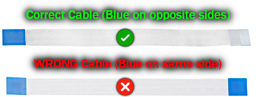
If you use the wrong type of cable it may not work and may damage some of the components on the board!
Finally, after you have checked everything, connect the USB charger to the base and power on. Check if the UV LEDs are lighting up, and the LCD panel flashes on. If the software is installed, shortly after it should switch off again, eventually starting the tracking software. From here you can give everything a quick test before the final assembly.
Once you`re 100% sure everything it working it`s time to finish the assembly. Take care to watch the video so that you choose the correct length of screws. This is especially important with the handle. you MUST use an M3*16 (17mm long) screw for these or you will screw into the battery!
This video shows you how to add some of the extra finishing touches, such as the black wires that you see sticking out around the tracker. They are purely for aesthetics, but are true to the original.
If you want to add a carrying strap to the tracker then it`s quite easy, and this video shows you how.
This video shows you how I removed the decals from the printed artwork and stuck them in place. A little bit of patience is required to get them to loo their best.
Given this would be battered around and should look like metal, I stole an idea from Adam Savage and used a chrome pen to draw silver lines on edges that would naturally get rubbed against stuff scratching the paint off. It`s quite effective as long as you don`t over do it.
It`s possible while building this that super glue has left a white residue mark on the plastic that won`t run off. It`s actually really easy to get off using nothing more than WD-40.
Don`t forget to join my Discord Server and share your builds, oh, and send me a tip to say thank you for providing all of this for free!
Copyright © 2025-2026 Robert Smith
Disclaimer: This guide is provided for informational and educational purposes only. While every effort has been made to ensure accuracy, the author accepts no responsibility for errors, omissions, or outcomes resulting from the use of this material. Building, soldering, programming, and operating electronic devices involve risks that include but are not limited to electric shock, burns, fire, or equipment damage. By following this guide, you assume full responsibility for your safety, your tools, your materials, and the final device. Always follow appropriate safety practices and proceed at your own risk.


