This guide is provided for informational and educational purposes only. While every effort has been made to ensure accuracy, the author accepts no responsibility for errors, omissions, or outcomes resulting from the use of this material. Building, soldering, programming, and operating electronic devices involve risks that include but are not limited to electric shock, burns, fire, or equipment damage. By following this guide, you assume full responsibility for your safety, your tools, your materials, and the final device. Always follow appropriate safety practices and proceed at your own risk.
This section covers soldering the various parts of the electronics, mainly the PCBs but also some of the other things you'll need.
When connecting any of the power wires, from/to the battery, to the Pi / PCBs etc, use a thicker wire, or, if you only have Dupont wires, use two for each connection (5V and GND).
Try to keep all power wires as short as possible. For the final connection to the Pi, as that is a header, keep those connections as short as possible. If you still have problems, remove the header and solder directly to the PCB.
Failure to get this right will cause power throttling and you will get a really slow framerate!
This is fairly straight forward, use the Dupont wires from the parts list, clip off the pin end, remove the plastic covering, and twist the wires nicely. Then tin the ends (apply solder and the iron either side of the wire and melt some solder into the wire). This makes it much easier later on.
Then, tin the contacts on the two variable resistors, (leave a little bit of solder behind)
TIP:: DON'T try to apply solder to the soldering iron tip and wipe it onto the component, it won't work!, you must apply it to the component and iron at the same time.
This is fairly straight forward, and you use the same technique as above. Choose the colouring of your Dupont wires carefully, I suggest using RED for positive, and BLACK for ground. Polarity is VERY important with LEDs.
This is almost identical to the UV LEDs except theres a common wire. 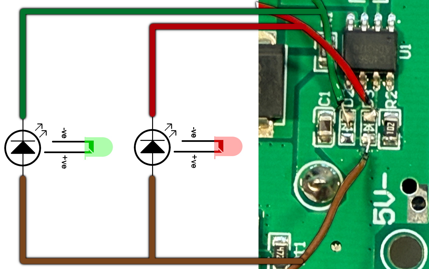
Soldering up the charge power supply board is a little more tricky, if you don`t have good soldering skills, skip this section all together. REMOVE BATTERIES WHILE SOLDERING TO THIS MODULE.
When using the heat gun, use a low speed or you will blow other part soff the board.
Please take time soldering the PCBs, and I advise you to do it in the same order as I have. Testing each connection with a multimeter is also very important, and the proper insertion and orientation of the FFC/Flat Flex cable is very important too. Assuming you have the correct type of cable (Type B or Reversed), then if you insert it the wrong way round it simply wont work. Connecting up your UV LEDs is an easy way to check for power!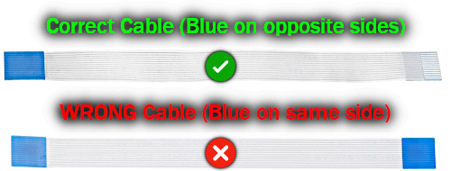
If you use the wrong type of cable it may not work and may damage some of the components on the board!
If you have any problems with connectivity, then you only really need to test these pins: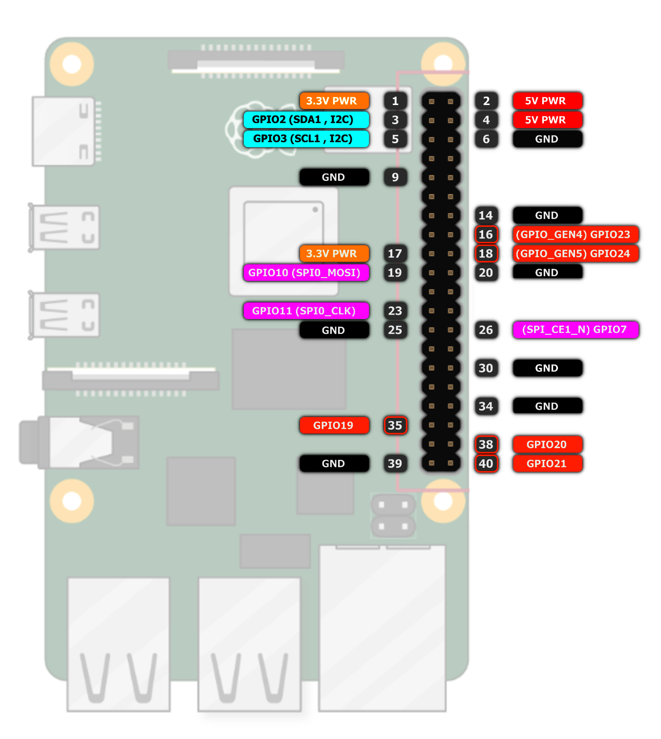
I've also marked the pins that need testing with a small circle on the PCB:
Copyright © 2025-2026 Robert Smith
Disclaimer: This guide is provided for informational and educational purposes only. While every effort has been made to ensure accuracy, the author accepts no responsibility for errors, omissions, or outcomes resulting from the use of this material. Building, soldering, programming, and operating electronic devices involve risks that include but are not limited to electric shock, burns, fire, or equipment damage. By following this guide, you assume full responsibility for your safety, your tools, your materials, and the final device. Always follow appropriate safety practices and proceed at your own risk.


